
HV Configuration
Note: The dedicated /hv page is available on builds with both -D ESPG_HV and -D ESPG_HV_ADC set (i.e. PWM HV generator and a real ADC feedback divider for live voltage readout). The ESPGeiger-HW kit ships with both enabled, as do the generic esp8266_hv and esp32_hv builds.
Builds with only -D ESPG_HV (PWM generator without feedback) expose the same freq/duty controls in the regular Config page rather than on a dedicated /hv page, since there’s no live readback to justify a real-time view.
The HV stage is a Pulse-Width Modulated boost converter circuit. By controlling the PWM duty cycle we produce a stable HV DC driving voltage for the Geiger-Muller tube - typically ~400 V depending on tube spec.
HV Settings
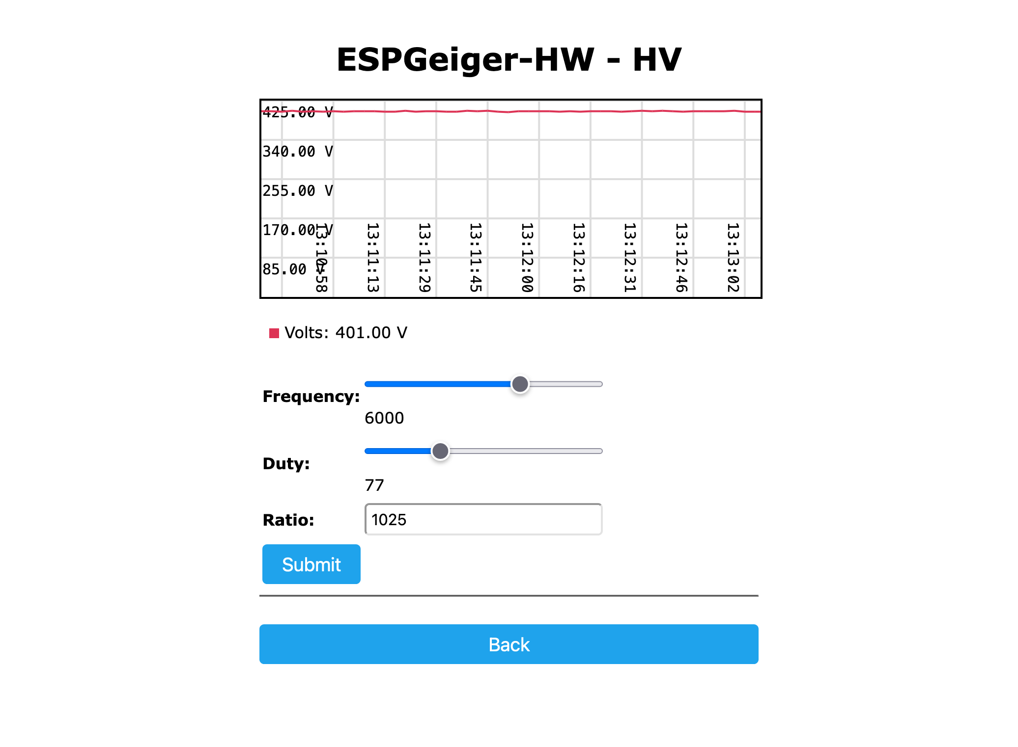
The /hv page exposes:
| Setting | Description |
|---|---|
Frequency | PWM frequency in Hz. ESPGeiger-HW max 9000 Hz; esp8266_hv max 40000 Hz; esp32_hv max 80000 Hz. |
Duty | PWM duty (1-1023, 10-bit). Each step is ~0.1 % of period. |
Ratio | Voltage divider scale factor - converts ADC counts to displayed volts. Calibrate with an external HV meter. |
Target | Auto-trim target voltage (0 = open loop, disabled). When non-zero, firmware compensates ±8 LSB to hold target. |
When changing settings:
- Always disconnect the Geiger tube before adjusting frequency or duty
- After submitting changes, the firmware briefly drops PWM low to avoid voltage spikes during the transition
- The closed-loop trim is suppressed for 30 seconds after changes so it doesn’t chase the transient
Calibration with a Multimeter
⚠️ HV is dangerous. 400 V at the tube is well above the let-go threshold and the boost-cap can hold charge after PWM stops. Wear gloves where practical, keep one hand in your pocket, and discharge the output cap with a 1 MΩ resistor across it before touching the rail.
A standard digital multimeter has roughly 10 MΩ input impedance. Probing the HV rail directly will load it down hard - you’ll read maybe 200 V on a supply that’s actually delivering 400 V into the tube - and the meter sees its full input rating rather than a scaled-down reading. The fix is a high-value series resistor in front of the meter that turns the meter input into the low side of a voltage divider.
Recommended probe: a single 1 GΩ resistor in series with the meter’s positive lead. With a typical 10 MΩ DMM the divider works out to:
V_HV / V_meter = (1 GΩ + 10 MΩ) / 10 MΩ ≈ 101
So HV ≈ DMM reading × 100 (close enough - the 1% offset is well within tube tolerance). For a 10× reduction (e.g. for a high-impedance bench meter) use a 100 MΩ series resistor instead. If your DMM input impedance is something other than 10 MΩ, plug it into the formula above.
Build the probe on an offcut of perfboard or inside a marker-pen case - keep the resistor body well clear of any conductive surface, since 400 V across a 1 GΩ part will arc to anything close enough. Use HV-rated wire (silicone test-lead wire is fine) and finish with proper meter probes at the user end.
Calibration procedure:
- Disconnect the Geiger tube. The tube is a current sink at threshold and will load the rail asymmetrically; calibrate against the bare boost output, not against the tube
- Connect your DMM (with 1 GΩ series resistor) between the HV rail and ground, set to DC volts, 20 V or 200 V range
- Open
/hv. SetRatio = 1andTarget = 0(open-loop, no trim chasing) - Adjust
Dutyuntil the DMM reads close to the voltage you want (HV/100 - so 4.00 V for 400 V) - Note the raw ADC counts shown on
/hvand your measured HV (DMM × 100) - Set
Ratio = measured_HV × 1024 / raw_ADC. The displayed reading on/hvshould now match your DMM × 100 - Once
/hvagrees with the DMM at one operating point, sweep duty over a couple of points to confirm the displayed voltage tracks the meter - if it does, the divider is calibrated - Reconnect the tube. Read the now-calibrated voltage on
/hvdirectly - no probe needed for routine checks - (Optional) Set
Targetto your desired voltage to enable the ±8 LSB closed-loop trim
If the displayed voltage drifts noticeably when you reconnect the tube, that’s normal - tubes draw a few µA at threshold and most home-built boost stages have non-zero output impedance. Set the open-loop Duty to give your target voltage with the tube connected, then enable Target to track it through temperature and age.
Generic HV Builds (esp8266_hv / esp32_hv)
These builds compile in the same HV management used on ESPGeiger-HW, but on stock ESP8266 or ESP32 boards. To use:
- Flash the appropriate
esp8266_hvoresp32_hvfirmware - Wire your boost converter circuit (transistor, inductor, output diode + cap, feedback divider)
- On first boot, HV is inactive (PWM pin defaults to -1) - no pin is driven
- Open
/egprefs, find the HV Hardware section - Set the HV PWM Pin to the GPIO connected to your transistor base/gate
- Save and reboot - HV will start up on that pin
- Open
/hvto set frequency, duty, and (after calibration) the auto-trim target
The ADC feedback pin is set per-build:
- ESP8266: hardware-fixed at A0 (only ADC pin available)
- ESP32: defaults to GPIO 36 (SVP / ADC1_CH0), input-only and ADC1 so no WiFi conflict. Override at build time with
-DGEIGER_VFEEDBACKPIN=NN.
Closed-Loop Trim
When Target is set to a non-zero voltage, the firmware automatically nudges duty by ±1 LSB every 10 seconds to hold actual HV near the target, with a 4 V dead-band so it doesn’t hunt on noise. The correction is bounded to ±5 duty LSB from your saved duty value, so a runaway feedback fault can only walk PWM 5 steps in either direction before stopping.
How many volts that bound translates to is up to your boost circuit. On a typical 400 V stage the V/duty slope is in the 2-5 V per LSB range, so ±5 LSB caps trim authority somewhere around ±10-25 V. The rule is: set the open-loop duty so that with the tube connected and Target = 0, HV is already where you want it - Target is for tracking drift, not for finding the operating point from the wrong place.
If you see the trim rail at its bound (visible as (trim +5) or (trim -5) next to the duty field), your duty pref is mis-calibrated - adjust it manually toward the rail direction until trim sits near 0.
The trim resets to 0 on reboot and on any duty/frequency change via /hv.