
Testing & Development
Pull requests are welcomed! Please visit GitHub if you would like to contribute to the project.
Pulse Testing
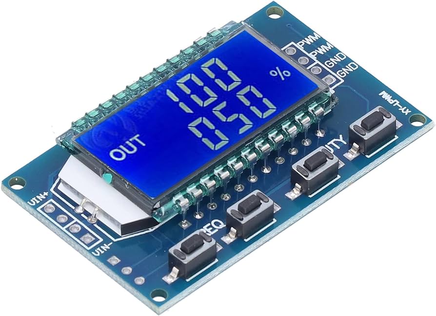
PWM modules like the above have come in handy whilst developing the counting logic.
Test Builds
ESPGeiger offers test builds specifically designed for ESP8266 and ESP32 microcontrollers. These builds enable the device to emulate various Geiger counter functionalities:
- Pulse Counter: Simulates the detection of radiation events by outputting a set number of pulses on the
TXPIN - GC10 Serial Counter: Emulates a GC10 Geiger counter, transmitting simulated radiation counts through the serial interface on the
TXPIN - MightOhm Serial Counter: Mimics a MightOhm Geiger counter, providing simulated radiation data in a MightOhm-compatible format via the serial port on the
TXPIN
Simulated values follow a Poisson distribution, mimicking the random nature of real radioactive decay.
By default the Test output cycles through several ranges of reading, switch each 5 minute period:
- 0.5 CPS / 30 CPM
- 1 CPS / 60 CPM
- 1.66 CPS / 100 CPM
- 2 CPS / 120 CPM
A build option is available to count the number of CPM sent on the local device, note that if this option is enabled and the RXPIN and TXPIN of the same device are connected together, counted values will be doubled unless the debounce window filters the duplicate - see below.
Emulation and Communication
In these test build modes, you can connect the TXPIN (transmit pin) of one ESPGeiger device to the RXPIN (receive pin) of another ESPGeiger device, either the same unit or a different one. This setup allows you to create a closed-loop testing environment, mimicking real-world Geiger counter communication scenarios.
TestPulse → esp8266_pulse cross-device setup
To sanity-check the end-to-end count pipeline, wire a *_testpulse device’s TX pin (default GPIO 12 on ESP8266, configurable via the Input preferences) to an esp8266_pulse device’s RX pin (default GPIO 13), and share GND between the two boards. Both devices then post to the WebAPI independently and their CPM readings should agree within Poisson noise.
Notes:
- Idle line level is LOW; each simulated count is a ~500µs HIGH pulse. The receiver counts on the falling edge at pulse end. This is inverted-polarity from a real Geiger tube (idles HIGH, pulses LOW) but the count is the same.
GEIGER_COUNT_TXPULSEis enabled in the default builds, so the transmitting device also counts its own outgoing pulses internally. On a bridged TX↔RX of the same device this would double-count except that the receiver-sidedebouncefilter (default 500µs) drops the duplicate edge that arrives immediately after.
Pushing the rate ceiling
Default settings give a practical ceiling of roughly 120k CPM on both sides:
- TX side:
pulse_width_uspref sets the simulated pulse high-time (default 500µs). Below the pulse width, the Poisson inter-arrival sampler saturates rather than producing overlapping pulses - the long-run rate is Poisson-correct up to that floor, then plateaus. - RX side:
debouncepref discards edges arriving closer than its value (default 500µs).
To stress-test beyond 120k CPM:
- Lower
pulse_width_uson the transmitting device (e.g. 100µs → ~600k CPM ceiling). - Lower
debounceon the receiving device to match or beat the new pulse cadence. - Optionally set
GEIGER_TEST_FIXEDCPMor use the--manualCPM setter so you’re testing a specific rate rather than the rotating 30/60/100/120.
The *_testpulseint variant uses a deterministic PWM (not Poisson) and scales cleanly to ~500k CPM without these knobs - useful when the goal is “does the counter keep up?” rather than “does the statistics look right?”.
Test build variants at a glance
| Build | Counting mechanism | Statistics | Max practical CPM |
|---|---|---|---|
*_test | Poisson ISR, no GPIO | Real Poisson | ~120k (debounce auto-zeroed on this variant) |
*_testpulse | Poisson ISR + real GPIO pulses | Real Poisson | ~120k default, higher with pulse_width_us lowered |
*_testpulseint | Uniform PWM | Deterministic (not Poisson) | 500k+ |
*_testserial | Per-second integer Poisson sampler + serial protocol | Real Poisson | not physically bounded |
TestSerial TX↔RX self-loopback is limited to 9600-baud protocols
Bridging TX to RX on the same *_testserial device for a self-loopback sanity check works cleanly for GC10 and MightyOhm (both 9600 baud) - you’ll see matching TestSerial TX: and TestSerial RX: lines in the log as the codec round-trips.
For GC10Next and ESPGeiger (both 115200 baud) the self-loopback is unreliable. EspSoftwareSerial bit-banging both directions on one chip at 115200 (8.7µs per bit) collides with WiFi / MQTT / loop() CPU work, so the frames corrupt in transit and the parser rejects them. TestSerial TX: still shows the correct outgoing line, but no matching TestSerial RX: line appears.
This is a SoftwareSerial limitation, not a codec bug - the same SerialFormat::parse_cpm round-trips cleanly at 9600, so we know the format/parse pair is symmetric by construction. Real hardware counters emitting to our SoftwareSerial RX at 115200 work fine because their hardware UART has precise bit timing; only the self-loopback scenario hits the limit.
To validate the 115200 path specifically, either run TestSerial on one ESP8266 wired to a second ESP8266 running real GeigerSerial, or trust the 9600 round-trip as evidence of codec correctness.
Note: No values are submitted to public services with Test builds.
Tick Profiling
For diagnosing performance issues in the 1Hz tick callback, add -DTICK_PROFILE to build_flags in your environment config. Once per minute the device logs a breakdown of where time is spent:
Tick profile: total=425 ctr=230 wifi=109 mods=128 lps=58733
Mods max: mqtt=61 sdcard=25
total- worst single tick duration in the last 60 seconds (us)ctr- max time ingcounter.secondticker()wifi- max time in WiFi tracking blockmods- max total time inEGModuleRegistry::tick_all()lps- loop iterations per second (steady-state health indicator)Mods max:- per-module worst-cases_tickduration, slowest first
Zero overhead when the flag is not defined - all instrumentation compiles out.